


Foxconn DigitaLife ELA P45 Motherboard

Board Layout
Â
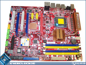
First impressions are usually lasting ones, and again it seems that the Foxconn ELA has received the same mismatched colour scheme that the A79A-S had. If you managed to read the Foxconn A79A-S review, you’d know that the colours did nothing for me then, and they still do nothing for me now.
Â
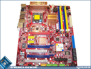
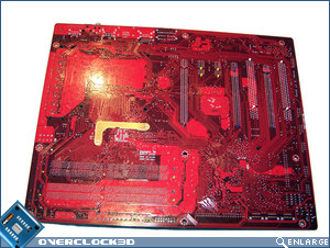
To Foxconn’s credit, they’ve managed to keep all of the available connectivity options of the motherboard within the ATX format. However, there are some caveats that come along for a ride when trying to cram so much motherboard onto such a limited space. Over the next few paragraphs I’ll attempt to highlight all of these to you as best I can. Turning to the rear of the motherboard I would like to direct your attention to the heatsink fastening systems that are present. You will notice that there is only one metal backplate for attaching the North Bridge heatsink to the motherboard and this uses spring-loaded screws which provide a better mount and surface contact for the chipset. All the other heatsinks are attached by the usual spring-load nylon pins.
Â
Â
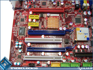
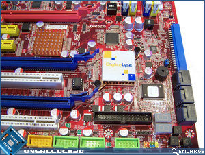
Beginning our tour around the motherboard at the expansion card slots, we can see that Foxconn has included three PCIe x16; two PCI, and two PCIe x 1 slots. The Foxconn ELA supports CrossFireX with each PCIe x16 slot providing 8x bandwidth, should you be using just two cards then the red and topmost blue slot will provide 16x bandwidth. CrossFireX support is made available due to an integrated IDT PCIe switch which can be found under the small copper coloured heatsink. If running a CrossFireX setup then you can expect to lose pretty much every expansion slot other than the second PCI x1 slot. Such is the scrifice required for running a multi-GPU setup. To the left of the expansion slots is a RealTek ALC888SDD, which provides both DTS Connect and Dolby Digital Live and drives the 6 audio jacks and the optical/coaxial audio connectors.
Â
Continuing on along the bottom edge of the motherboard we have the front audio; CD_In; SPDIF Out; 1x IEEE 1394; 3x front USB; IrDA; front panel and FDD connector. Personally I’m not a huge fan of the FDD plug being anywhere other than the leading edge of the motherboard, but considering that it’s a seldom used connector these days, it becomes less of an issue. IEEE 1394 support is provided by a VIA VT6306 chip which is visible to the left of the middle PCIe x16 expansion slot.Â
Â
Â
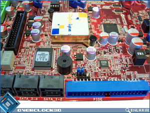
In the bottom right hand corner of the motherboard we have the PWR/Reset/CLR_CMOS buttons; digital de-bug LED’s; 6x right angled SATA ports and the IDE port. The SATA ports are controlled via the ICH10 chipset and a JMicron JMB363 Host Controller which can be seen above the South Bridge. Also present here are an onboard speaker; AMIBIOS flash ROM; Fox One chip (monitors critical motherboard components) and CLR_CMOS jumpers. The South Bridge bears the DigitaLife logo and is passively cooled by a low profile copper heatsink.
Â
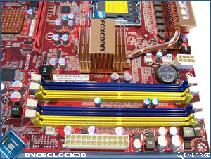
Moving up the right hand side of the motherboard we have the 24-pin ATX Power connector and four DDR2 DIMM slots. The DIMM slots are powered by a single-phase analog PWM circuit which is more than sufficient for DDR2 and are able to accommodate 8GB of DDR2 memory. Due to the slightly cramped conditions on board, when installing a full length graphics card in the top PCIe x16 expansion slot it means that the RAM retention clips foul on the graphics card PCB. It’s not a major issue, but if you swap out RAM frequently it may become one. Immediately to the top left of the memory DIMM’s we have the system battery compartment and the ATX 12V power connector.
Â
Â
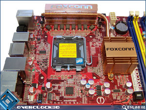
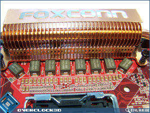
Moving around to the CPU socket area we can see the new position for the P45 North Bridge chipset and passive heatsink. Due to the inclusion of 8 phase Digital PWM it means that the CPU socket remains relatively clean, however the North Bridge heatsink may become an issue with aftermarket CPU cooling solutions. A copper heatpipe connects both the North Bridge heatsink and PWM heatsinks in an effort to maximise cooling efficiency. The Foxconn ELA uses FP4-200 0.200UH 30A Ferrite chokes which can be seen in front of the large rectangular heatsink which cools the Digital PWM’s.
Â
Â
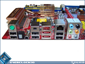
The rear I/O panel features a plethora of connectivity options. A legacy PS/2 mouse port is there along with six USB 2.0 ports. The two eSATA ports and the FireWire port provide plenty of high-speed access while the coaxial, optical and 6 audio jacks enable many different audio outputs. The somewhat surprising single gigabit Ethernet port is powered by a RealTek RTL8111C controller.
Â
Â
Well that concludes our trip around the Foxconn ELA, and I must confess that although the layout is somewhat ‘different’ to what we’re used to, it makes use of the limited space available quite well. Let’s head over the page to check out the Foxconn ELA’s BIOS.