Published: December 22, 2008 |
Source:
MSI |
Author:
Rich Weatherstone
MSI X58 Platinum Motherboard
Board layout & Appearance
MSI motherboard’s of old have been a kaleidoscope of colours with pink ram slots being the bugbear of fashion freaks everywhere. This time around, although there is a splash of colour here and there the theme is a lot more co-ordinated, with blue, black and white slots now dominating the black PCB. The rear of the board has a holding backplate for the CPU socket area which may prove troublesome for those wishing to use a CPU cooler backplate.
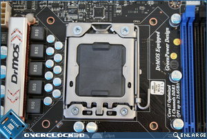
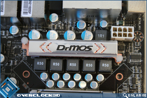
The CPU socket area itself is relatively uncluttered with the Mosfets situated to the left of the socket. Notable by their absence are the uppermost Mosfets. This is due to the ingenious DrMOS which is an integrated Driver-Mosfet allowing a 30% reduction in power and increasing efficiency to a reported 93.1%. Impressive figures which we will be keen to see if it actually makes a difference in the power consumption test later in the review.
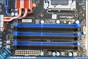
The 2-Phase, Triple channel DDR3 slots utilise APS technology, again to improve power efficiency and raise the voltage adjustment table levels up to 128 levels. The slots however only officially support ram up to 1333mhz and 24GB in total so it will be interesting if this can be pushed higher as our test rig ram kit is 1600mhz. Thankfully MSI have finally done away with the wretched pink ram slots and replaced them with royal blue. While this wont affect performance it is easier on the eye and ties in much better with the overall theme of the board.
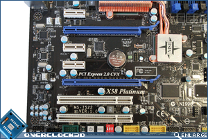
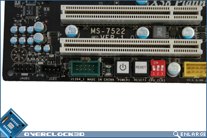
The PCI area is well laid out from top to bottom: PCIe x1, PCIe x16, PCIe x1 (x2), PCIe x16 and PCI (x2). With plenty of space between the two PCIe x16 slots Crossfire should not present a problem even with dual slot cards. SLI however would be a problem on this board, as at the time of writing, this version of the Platinum does not support SLI. Unfortunately, you will need to spend a little more cash to get the SLI version if you favour the NVidia camp.
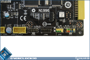
The bottom of the motherboard is where most of the goodies are. To the right of the board are the quick ‘M connectors’ allowing easy connectiion of those pesky motherboard headers. Further along we see two USB headers and a Firewire header. Nestled between are the tools we’re most interested in. The Power and Reset buttons are straightforward enough and while very welcome are now commonplace among high-end motherboards. The traditional dip-switches though are a throwback to yesteryear when the only way of overclocking a motherboard was by said switches. If they perform as well as they did on the recent AMD board we tested then I will be impressed.
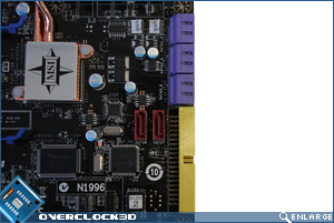
To the right of the motherboard we see the 6 SATA ports which are conveniently positioned at 90 degrees so they will not interfere with the uppermost PCIe slot they are inline with. For whatever reason MSI have seen fit to stick with purple sockets and it gets worse – a yellow IDE slot sits just below them. This clash of colour is puke-worthy and needs addressing as it destroys the overall look of the motherboard. To the left of the IDE slot we see an extra two SATA slots.
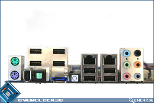
The I/O area thankfully is much cleaner in appearance and with 8x USB ports, 2x LAN ports, 1x Firewire, 6x 3.5mm jacks and 1x S/PDIF optical port even the most discerning enthusiast will be satisfied. But thats not all, also situated conveniently on the I/O backplate is a CMOS clear switch which will be a godsend for those who intend on pushing this board beyond the boundaries it was designed for.
Both the Northbridge and Southbridge heatsinks are modest in appearance thanks to the Northbridge no longer having to deal with the memory controller. With copper used throughout and both heatsinks being connected via dual heatpipes, cooling should not be an issue. Incidentally, MSI claim an average temperature of around the 45 degree centigrade mark.
Removing the chipset coolers was a little tiresome due to the ‘cement like’ thermal interface material MSI insist on using. If you intend on removing the heatsink yourself I would advise on loosening the TIMs grip by heating the sinks up a little beforehand.
Here we see the X58 core and ICH10r controller in all their nakedness. The mounts, despite the push pin design on the heatsinks were quite good and while I am not a fan of push-pin designs they do seem to have done the job right this time around.
Enough of the pretty pictures, let’s fire this baby up and head straight for the BIOS…


