Scythe Kaze Master Fan Controller
Installation
Â
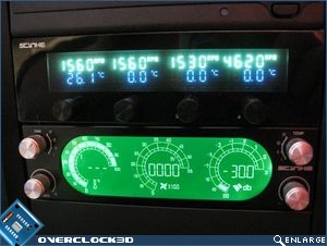
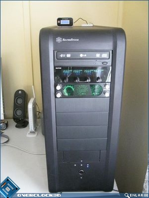
 I’m not going to bore you with the in’s and out’s of installing the Kaze Master as it really isn’t difficult, but I will give you a very brief run-down for the sake of posterity. You will see that I have installed both the Scythe Kaze Master and the Kama Meter to illustrate how they differ from each other and how they compliment my chassis. Please excuse the slightly fuzzy images of the Scythe Kaze Master. The green text is quite bright and seemed to confuse the light sensor in my Canon IXUS 950IS.
Â
Installation-wise, I have always found it best practice to route the fan cables and thermal probe wires first as it makes sense to get the fiddly bits out of the way first. Use the tape supplied by Scythe to stick down the thermal probe in your chosen location, just make sure you remove any accumulated dust first. I’m a bit of a neat freak when it comes to cabling so a little more time spent routing the cables properly will give a better overall finish in the long run.
Â
Once you’ve finished routing the cables remove a spare 5.25″ drivebay cover, or 3.5″ if you have the smaller version, and set the cover aside. Feed the fan/thermal probe/power cables through the opening left by removing your drivebay cover and slowly connect all the cables to their respective headers. You might want to make a note of what probe and fan cable corresponds to which channel on the Scythe Kaze Meter too. I connected the three 120mm fans on my Thermochill PA120.3 radiator to the fan controller, and the RPM lead off my Laing DDC Ultra pump which you can see from the image above. For this review I also connected one thermal probe to allow me to check the calibration of the temperature sensor in the unit. The thermal probe is sitting roughly in the centre of my Silverstone TJ-07 and is measuring case temperatures inside.Â
Â
Â
Once everything is connected then you are free to install the Scythe Kaze Master into position with the included screws. Make sure that the face of the unit finishes flush with the leading edge of your chassis and/or the drivebay cover below it. Tighten off the screws and viola…you’re done! Fire up your rig and check that all the hardware that you have connected is being monitored properly. If it isn’t, the RPM monitor (top row) will flash depending upon which channel isn’t connected or reading properly, and the included alarm will squawk annoyingly until the problem is rectified. You can disable the alarm by removing the jumper pins on the PCB, but it kind of defeats the purpose of having an alarm.
Â


